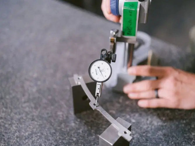
Prototype revisions are a normal part of product development. The trouble begins when changes are made without a full look at how they affect tooling, material behavior, secondary work, and inspection. For custom stamped metal parts, a small update in the CAD file can create a much larger change on the production floor.
We help OEM teams separate useful design refinement from changes that can slow manufacturing readiness. As November planning gets underway, teams preparing for first-quarter launches, annual sourcing decisions, or year-end engineering milestones should review whether their prototypes are stable enough to move toward production tooling and capacity planning.
A stamped part is not simply a shape cut from metal. Its success depends on how the geometry, material, tolerances, tool sequence, finishing steps, and inspection needs work together. When one of those pieces changes, we need to assess the full system before the change becomes locked into a die design.
Function should guide prototype decisions before appearance or early CAD assumptions. Hole placement, formed features, mounting points, load needs, and mating-part interfaces all affect whether we can stamp a part consistently at production volume.
Early in the process, we recommend identifying dimensions that directly affect how the product works. A feature may control assembly fit, electrical continuity, safety, or structural strength. When you clearly flag that priority, we can recommend practical limits, measurement methods, and tool details that support the intended result.
Useful functional information can include:
Late function changes can cause more disruption than expected. Moving a hole closer to a bend, tightening a flatness callout, or adding a tab near an edge may require a new strip layout, another operation, or a different tooling method. Rather than sending dimensional targets alone, share the performance outcome you need. That gives us a clearer path to recommend how custom stamped metal parts can meet the need at scale.
One of the most common prototype issues we see is a tolerance that made sense for an early sample but does not reflect stamping conditions. Machining, laser cutting, and manual forming can create prototype results differently than a high-volume stamping die. A measurement achieved during early development should not automatically become the production requirement.
Tolerance reviews should account for material thickness, alloy behavior, feature location, forming difficulty, and expected volume. Some tight limits are necessary, especially at critical interfaces. Applying those same limits across every feature, however, can add inspection burden, increase scrap exposure, and make the tool harder to build and maintain.
Before a design is frozen, a tolerance analysis can help your team sort out what truly needs close control. We can work with you to consider:
This type of review supports repeatability. Instead of discovering a capability concern after a tool is underway, you can adjust the prototype while changes are still easier to manage. Clear tolerance decisions help us plan inspection requirements that match the way the part will actually be produced.
A small geometry change can reshape the entire die strategy. Bend angles, radii, slot shapes, embosses, louvers, tabs, and edge conditions may change the number of operations needed or the sequence in which the part is formed.
Features near bends, corners, and formed areas deserve extra attention. For example, moving a pierced hole, shortening a flange, or reducing a bend radius can affect material flow. It may also raise the chance of distortion, cracking, burrs, or interference with tooling components. Depending on the design, we may need to reconsider whether a progressive die, transfer die, or secondary operation is the better fit.
Part nesting and strip layout can be hidden concerns during prototype review. A profile change may alter material yield, press tonnage, feed progression, or cycle time. Material grain direction can matter as well, particularly when forming requirements are involved. A change that improves the look of a part may reduce manufacturing efficiency if it has not been reviewed through a tooling lens.
When revisions are needed, send updated CAD files with clear notes explaining what changed and why. A disciplined engineering change process allows us to evaluate effects on tooling, quality planning, lead time, and production flow before commitments are made.
Material substitutions affect far more than appearance or raw material selection. A change in alloy, temper, thickness, coating, or finish can influence formability, springback, weldability, corrosion resistance, conductivity, and dimensional consistency.
Stronger materials may require more forming force and can spring back differently after bending. Coated materials may need careful handling to prevent surface damage. In either case, die clearances, press settings, deburring methods, and inspection criteria may need to change along with the material specification.
Finishing steps should be part of the prototype plan from the beginning. Plating, powder coating, painting, heat treating, and deburring can affect final dimensions, hole fit, masking needs, and how parts stack for shipping. A part can meet requirements before finishing but miss them after the final process if those effects were not considered early.
For custom stamped metal parts, the best material and finish choice balances performance, repeatability, supply availability, and manufacturability. Reviewing those decisions as one connected system helps prevent surprises after a prototype has already been approved.
Successful prototype changes are not avoided altogether. They are reviewed early, documented clearly, and discussed with a manufacturing partner that understands tooling, materials, secondary operations, and inspection. During year-end planning, we encourage you to review open revisions before committing to production tooling or first-quarter capacity.
Bring together the latest drawings, revision history, material specifications, annual volume expectations, and performance requirements for one final manufacturability review. A stable prototype does not mean every detail is perfect. It means the remaining decisions are understood, the functional priorities are clear, and the production path has been considered before a change turns into a tooling delay or quality concern.
Banner Metals Group Inc. helps you evaluate custom stamped metal parts with manufacturing realities in mind, from material selection to tooling considerations. Our team can help clarify open questions and identify practical next steps for your design. Contact us to discuss your project and request guidance from experienced stamping professionals.
Burr control in aerospace metal stamping begins long before a part reaches final assembly. A small raised edge may look minor, but it can interfere with fit, fastener seating, seals, electrical insulation, moving components, and safe handling. When a stamped part is part of a tightly controlled assembly, edge condition deserves the same attention as the part’s other required features.
We focus on repeatable edge quality because aerospace programs often depend on parts performing the same way from the first production run through later releases. That means reviewing the full burr-control path, including material selection, tooling, press setup, deburring, inspection, and production records. October can also be a useful time to review process readiness as suppliers prepare for year-end build schedules and upcoming program needs.
A burr is raised, sharp, or rough material left along an edge after cutting, piercing, blanking, or forming. Burr height matters, but so do burr location and direction. A burr facing outward from a tab may create a handling concern, while a burr inside a pierced hole may affect fastener seating or the fit of a mating component.
During aerospace metal stamping, burrs can form for several reasons. Some are tied to the material, while others relate to tooling condition or press setup. We review these factors early because one source of variation can carry through the rest of the manufacturing process.
Common causes include:
Not every stamped edge needs the same finish. A hidden edge with no assembly contact may have different requirements than an edge near a seal, connector, moving mechanism, or fastener. We base burr acceptance on the part print, customer requirements, functional needs, and applicable program specifications instead of treating every edge the same.
Clean stamped edges start with tooling designed for the material and the part geometry. Proper punch and die clearance supports a controlled shearing action. If clearance is too tight or too loose, the edge can show excess rollover, a larger fracture area, or a more pronounced burr. The right clearance depends on factors such as material type, thickness, temper, and the shape of the feature being cut.
Tool condition also has a direct effect on edge quality. Sharp, correctly aligned punches and dies produce more consistent results than worn tooling. As tools wear, burrs can grow, edge quality can shift, and variation can appear between production runs. Regular tool review helps us identify when maintenance is needed before a part moves outside its required edge condition.
Press setup needs equal attention. During production, we monitor the conditions that can affect the stamped edge, including:
These controls work together. A well-maintained die cannot fully offset a poor press setup, and a properly set press cannot make up for worn cutting edges. By managing both, we can reduce burr formation at its source rather than relying only on later finishing steps.
Stamping alone may not always produce the edge condition needed for assembly. When that happens, secondary deburring can remove sharp or disruptive material before the component moves downstream. Depending on the part and its requirements, we may consider mechanical deburring, vibratory finishing, brushing, hand finishing, or another process suited to the feature and material.
The goal is not simply to make an edge feel smoother. Deburring must remove the unwanted burr without rounding a required corner, changing a hole size, thinning a delicate section, affecting formed features, or harming surface requirements. Aerospace parts may include narrow tabs, small pierced holes, thin walls, or closely controlled profiles, so the finishing method must match the design.
Process order matters as well. A part may need deburring before dimensional inspection so measurements reflect its final edge condition. In other cases, deburring needs to happen before coating, machining, or assembly so later operations do not conceal a burr or create another edge issue.
A controlled approach often considers:
Inspection confirms that burr removal did not change the part in an unwanted way. Dimensional checks can help verify hole sizes, edge profiles, formed features, and other specified characteristics after stamping and finishing. Visual reviews, tactile checks where appropriate, magnification, and gauges can also help identify burrs in areas that are easy to miss, such as pierced holes, slots, narrow tabs, and formed edges.
Clear work instructions support repeatability across production. First-piece reviews, in-process checks, and final inspection records show that edge-quality requirements were addressed throughout the run. Documentation also gives production teams a consistent reference when a program calls for a particular edge condition, inspection method, or finishing sequence.
Addressing burr requirements during quoting and design review, before tooling is finalized, helps establish appropriate controls for material, tooling, finishing, and inspection. Understanding how edge condition affects fit, function, safety, and downstream operations can reduce rework and support consistent aerospace assembly results.
Banner Metals Group Inc. provides aerospace metal stamping services tailored to demanding component specifications and production requirements. Our team works with customers to support reliable, repeatable stamped parts from initial review through production. To discuss your next project, contact us today.